This Page is an Extension of Erwin's SG Work Shop
Circuit Schematics with
little intro. and how I ended up in the Bedini Circuit:
Most
folks who have little experience in electronics aren't able to read
schematics let alone soldering components onto a circuit board to get a
working gadget. I am one of them. I am a Swiss Tool and Die Maker, have
therefor little knowledge in electronics. Looking at a schematic, it is
evident that applying the proper mechanical and practical technique one
can't possibly work it correctly without experience and proper
schooling. Soldering components through a board did not work for me. I
remember John's comment, the closer everything is soldered together,
the better it works. Not until I omitted the board did it finally work.
Once I figured out by trial and error, how to solder up the John Bedini
Circuit, I made drawings for easy visualizing of the different
soldering joints and component arrangements. Image 3 and 4 are such
drawings. Click on them, select all, copy and paste into Word, if
you do not have Windows Picture Tool in your
browser, go to Windows View menu, tool bar, check off picture
tool bar, click on text wrapping, click through, on the main tool bar
reduce page size on your main bar from 100% to 25% go back to picture
tool bar and click format picture (paint pail) size tab, scale from
!00% to 80%, go to rotate left 90 degrees on the same tool bar, click
to neutralize ------> print. What is a drawing good for if you can't
read it? I know there are people who do not know how to extract and
copy readable drawings out of a computer! I was one of them just a few
months ago.
I hadn't known the difference between
a resistor and a capacitor or what the function of a transistor was. So
when I stumbled into the peswiki.com/index site and found the following
Bedini forum in January 05:
http://groups.yahoo.com/group/Bedini_SG/messages/
I could not help noticing the very negative behavior of some people obviously with second agendas. With other words; if you nullify in your mind any negative comment concerning the Bedini technology or any subject for that matter, then you'll get some where. I learned not to open up any closed files(if you do, keep track of it) from those groups or individuals after I ended up with three Trojan horses and a I-Worm/Bagle in my AVG virus vault. All negativeness stems of the opponent and everything positive is God our Creator.
These are Rick's groups:
http://groups.yahoo.com/group/Bedini_Monopole/
http://groups.yahoo.com/group/bedini_monopole2/
So, when Rick Friedrich started his Bedini Monopole Group on February 26 - 05, I was all "gong ho" and joined in. Message 51 was my first post. Rick is doing a fine job by the way.
I have to admit that I was one of the many who asked John Bedini per email years ago how to build a coil and where to get the material needed, to which of course I too, never got an answer. I suspect this was part of the reason why JB is encouraging the group efforts. I was on the lookout a number of years, how to get into the Bedini Circuit and finally found it. While reading all those messages, I realized that upgrading was my only chance to get anywhere. So I bought myself the book "Practical Electronics for Inventors" by Paul Scherz, McGraw-Hill, No. 3105 for $39.95 US http://www.lindsaybks.com/ 815 935 5353 fax 935 5477 (ask for catalog) and away I went. This book is for hands on electronics and worth every dollar, a must for the beginner. I expect of you to go the same route. You need to have at least knowledge about the function of the individual electronic components, in order to succeed, since step by step instructions for free are hard to come by; although better now with the Internet.
Other sources for the book:
http://froogle.google.com/froogle?q=%22Practical+Electronics+for+Inventors%22+by+Paul+Scherz,+McGraw-Hill&hl=en&lr=&sa=X&oi=froogle&ct=title
http://www.amazon.com/gp/product/0070580782/103-7538866-9686215?v=glance&n=283155
http://www.powells.com/cgi-bin/biblio?inkey=65-0070580782-1http://groups.yahoo.com/group/Bedini_SG/messages/
I could not help noticing the very negative behavior of some people obviously with second agendas. With other words; if you nullify in your mind any negative comment concerning the Bedini technology or any subject for that matter, then you'll get some where. I learned not to open up any closed files(if you do, keep track of it) from those groups or individuals after I ended up with three Trojan horses and a I-Worm/Bagle in my AVG virus vault. All negativeness stems of the opponent and everything positive is God our Creator.
These are Rick's groups:
http://groups.yahoo.com/group/Bedini_Monopole/
http://groups.yahoo.com/group/bedini_monopole2/
So, when Rick Friedrich started his Bedini Monopole Group on February 26 - 05, I was all "gong ho" and joined in. Message 51 was my first post. Rick is doing a fine job by the way.
I have to admit that I was one of the many who asked John Bedini per email years ago how to build a coil and where to get the material needed, to which of course I too, never got an answer. I suspect this was part of the reason why JB is encouraging the group efforts. I was on the lookout a number of years, how to get into the Bedini Circuit and finally found it. While reading all those messages, I realized that upgrading was my only chance to get anywhere. So I bought myself the book "Practical Electronics for Inventors" by Paul Scherz, McGraw-Hill, No. 3105 for $39.95 US http://www.lindsaybks.com/ 815 935 5353 fax 935 5477 (ask for catalog) and away I went. This book is for hands on electronics and worth every dollar, a must for the beginner. I expect of you to go the same route. You need to have at least knowledge about the function of the individual electronic components, in order to succeed, since step by step instructions for free are hard to come by; although better now with the Internet.
Other sources for the book:
http://froogle.google.com/froogle?q=%22Practical+Electronics+for+Inventors%22+by+Paul+Scherz,+McGraw-Hill&hl=en&lr=&sa=X&oi=froogle&ct=title
http://www.amazon.com/gp/product/0070580782/103-7538866-9686215?v=glance&n=283155
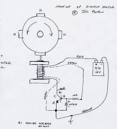
John Bedini's
SG North-Pole Motor, a gift of him to the people and their
betterment
for learning, testing and self preservation.
for learning, testing and self preservation.
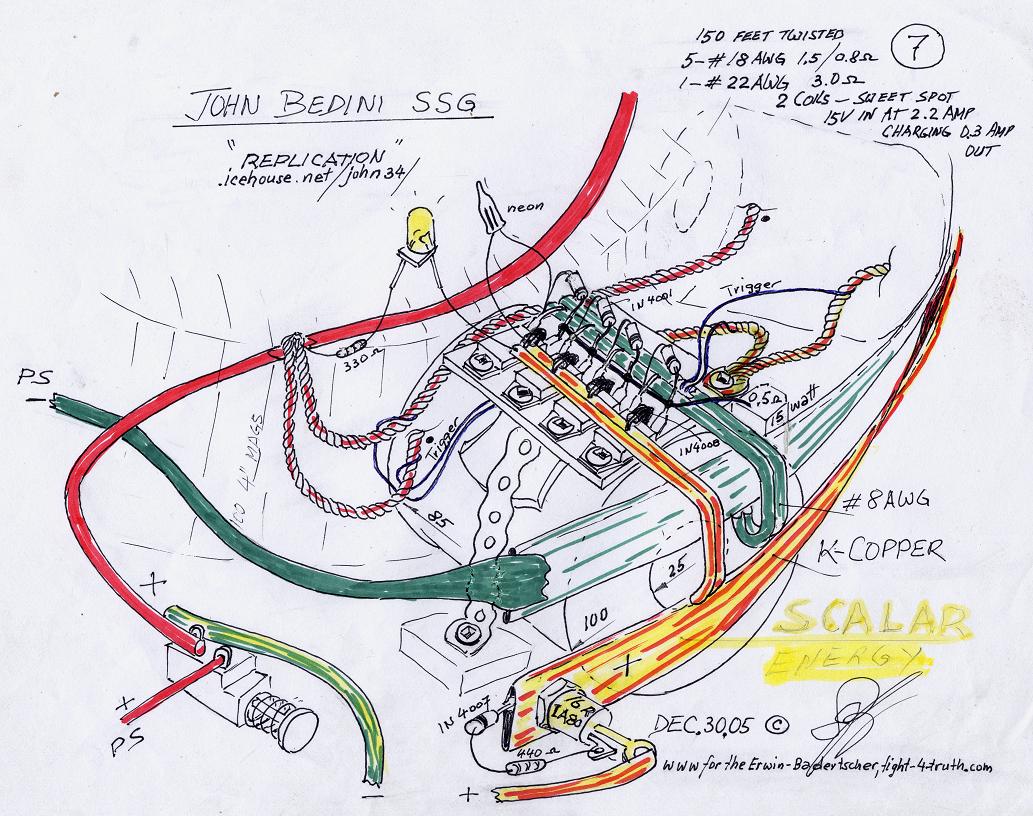
Image 1 (SSG)
1a (see Image 11 and 12)
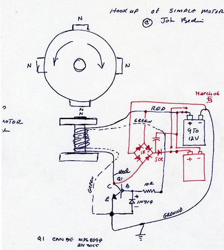
Image 2 (SSG)
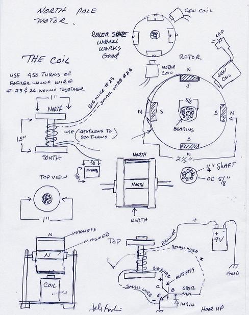
Image 3
(SSG) This
is what you start out with if you are new to the Technology. At
the same time I am pointing out to you a mistake I made out of
slow comprehension. Since the
2N3055 tophat transistors
have only two terminals "base" and "emmiter" the mounting base in is
also
the collector terminal, I got into the habit by placing the coil power-
strands to the heat sink which is the collector and case of the 2N3005.
Consequently when I moved on to the BD243C I
connected to the heatsink instead the proper transistor collector
terminal. Interestingly I haven't noticed much difference even when it
comes to soldering the strand to the proper transistor terminal,
Image 6 Bedini/Cole circuit! Image 8 is a different story, this is the
SSG icehouse set up. Having 6 strands in my SSG's coils, I took
the coil wire return off of the heat sink (collector plate) and took 5
of the individual strands and soldered them behind the 1N4007 at
the collector terminal of the MJL21194's which improved the
pressure into the batteries but not necessarily the charging rate.
To blow out of the water
what i just said, my latest tests with my newest SSG revealed better
performance by mounting all six wire strands to the heat sink. Pulsing
caps is obviously the answer.
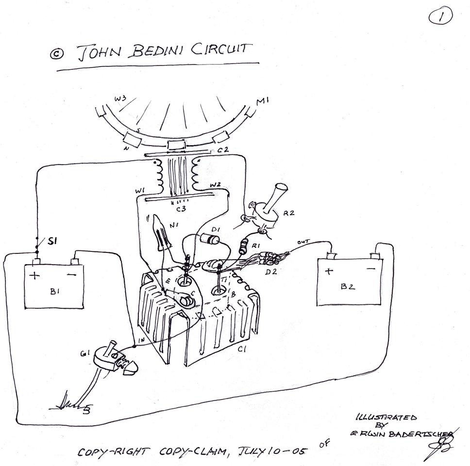
Below is list of the letter/numbers on my drawing #1 Image 3, starting down from the top:
W3--- Wheel
M1--- Ferrite Magnets
R2--- Coil
W1--- Drive winding, big wire
W2--- Trigger winding, small wire
C3--- Core, Lincoln R60 AWS 1/16 or tie wire
N1--- Neon bulb
D1--- Diode 1N4007
R2--- 1K potentiometer (use wire wound)
R1--- 10 Ohm resister
D1--- 1N4007 cluster
T 1--- 2N3055 upside down inside an aluminum heat sink with protruding anode and cathode
C1--- Heat sink
G1---Ground rod
Image 4 (SSG)
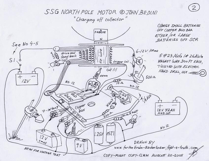
Image 5 (SG)
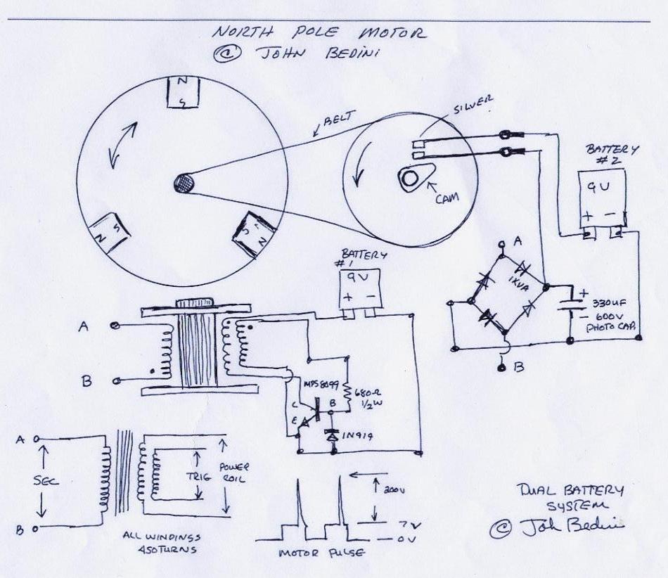
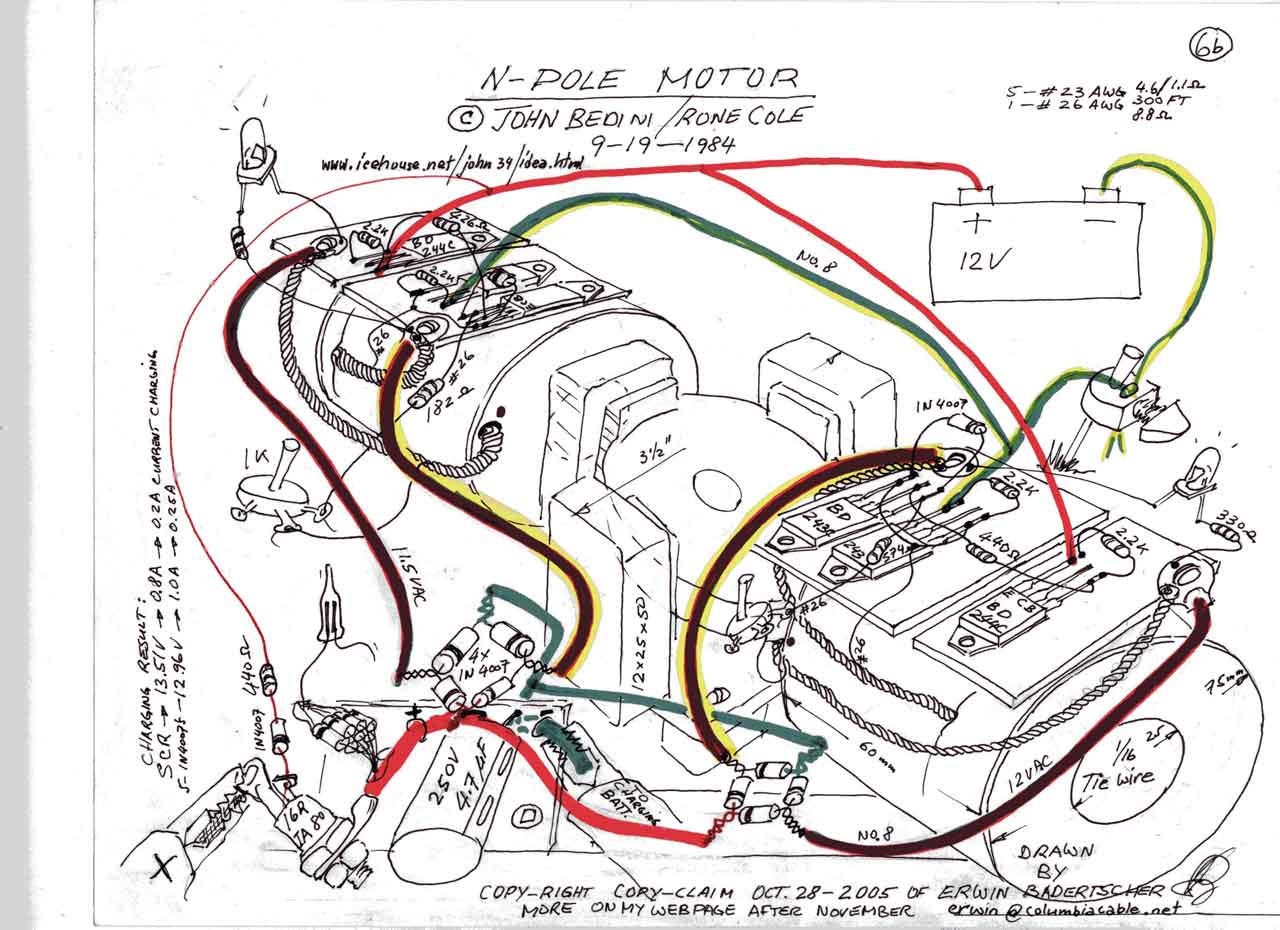
http://www.icehouse.net/john34/idea.html
Image 6aa Compare Image 6a and 7 with this one.
Image 6 (SSG) Image 6aa above, is the base for my drawings # 6a, 6a "update" and 6b.
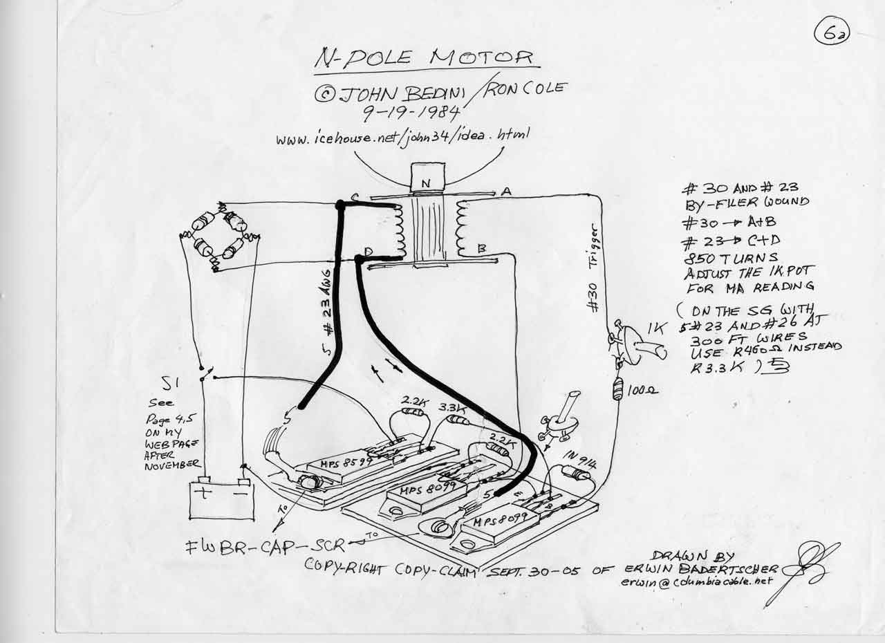
Image 6a (SSG) Can you tell me what the mechanical difference is between these two drawings?
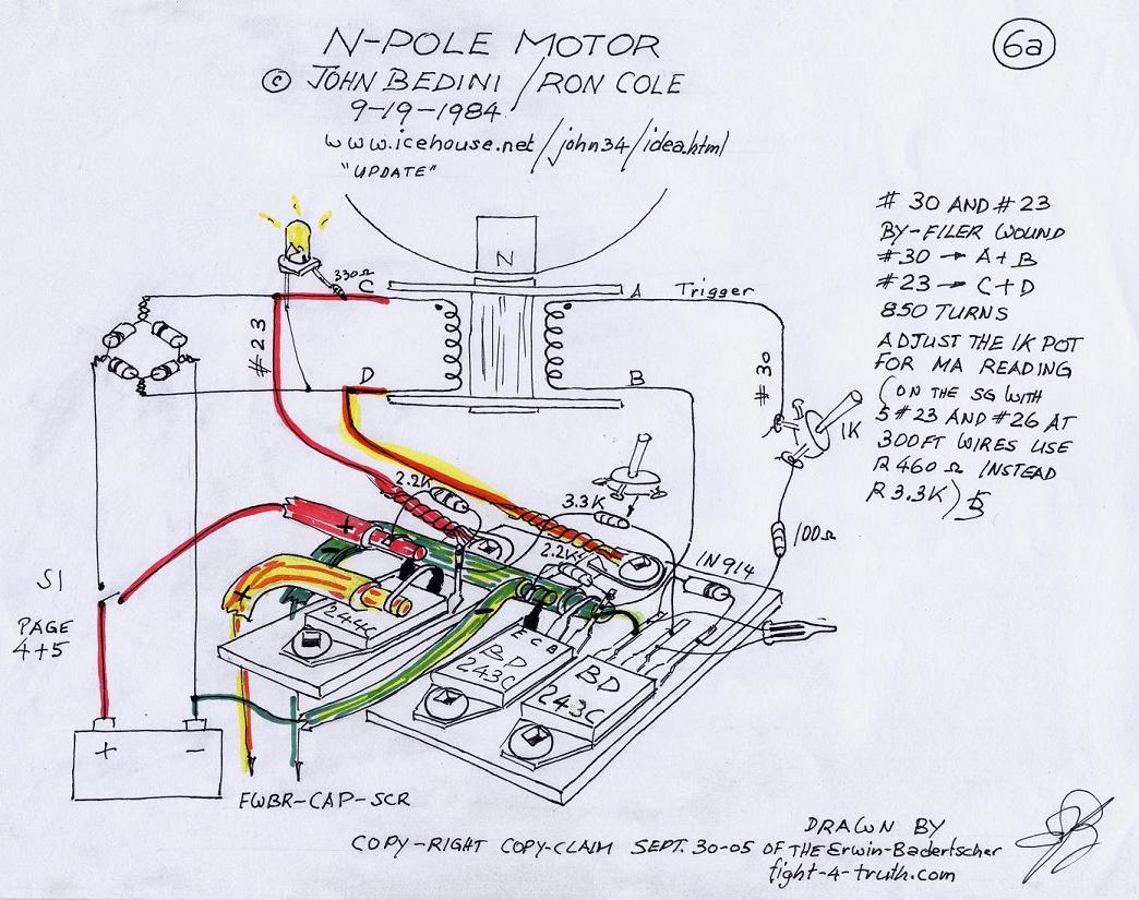
If you
look at the transistor terminals, you'll see that in the upper drawing,
the transistor terminals are not being used, whereas in the update, I
took the positive and negative bus bars (wires) instead from the heat
sink plates, directly off the transistor collector terminals. Hence
drawing the energy from the plates alongside the collector p-type semi
conductor, which is sandwiched between two n-type semy conductors of
the bipolar transistors, which causes some electrons to jump from the
emitter side through the base region into the collector side, causing
an increase in base voltage and emitter to collector electron flow,
which at the same time is causing positive current flow from collector
to emitter, which could be the cause of less positive current heading
for the charging side, better scalar energy flow and higher RPM.
Image 7 (SSG)
Cover all your batteries while charging, very important for safety, hitting a battery with too big of a voltage spike might be enough cause to explode it!!! Meaning acid everywhere and possible injury, so better be save than sorry.
Image 8 (SSG)
Switching
the "Big Six or Eight"
In continuation of the replication page, I must tell you that I changed a few things around. First I removed all the wires from my 8-coiler, left two coils and removed the others. Squashed a couple of 1/2" copper pipes, didn't have any 3/4 K-copper, which is the stuff the plumbers use for H2O house service lines (heavy wall pipe, match the cross sections of the twisted wire), then I soldered up four transistors according image 8 above, used two #8 wires for bus bars off the transistor terminals, pos. and neg. each, ensuing the two coils in parallel and set everything up. Anyhow I'm getting ahead of myself, the drawing above is the result of my new setup.
Another reason for piggy backing a second coil to one plate is having looked at the "Big Boy".
Looking at the book, multiplying the single SSG transistor did not make any sense to me at first, until I mounted all four on the plate and studied the setup. That some transistors have a negative resistance region, has come across clearly, but how to comprehend it, is another thing. Never the less, perhaps picking the energy up through the switching transistors into the bus bar, instead direct off the plate, like I have been doing it, might speed up the whole operation. Realizing that two or more bipolar transistors hooked up in parallel might have an amplification effect like a differential amplifier, which would not really surprise me knowing that John Bedini is a specialist in transistor amplification. Thus I hooked up the four transistors and everything according my feelings (the Lord's help), with the same ohm setting for max. VAC output off the coils (from before with one transistor setup only, since I never managed the wheel to reach the sweet spot) and gave the 12" 8-mag wheel a good spin by hand. When I flicked the switch, the wheel took right off like I gave it a kick and so did the needle of the charging voltmeter. At first the motor drew 4.5 amps then it dropped down to 3.8 then to 3.0 then it settled to the sweet spot at 2.5 amps just-a-hummin.. with a charging reading into the batteries at 0.3amps. Besides my pounding heart of joy, I was getting quite worried, whether my feeble wheel would stand this high RPM with those big magnets, the mags didn't have much gluing surface and my copper strapping was not very tight either... it was really creating wind. I ran it for about an hour, taking some readings at 4.30 in the morning.
Image 8a
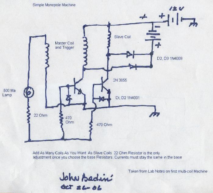
You can see that I am not to far off by this next image 8a, which is the basic (small) proper schematic for this machine (Icehouse) which John Bedini just gave out. It also testifies of the forgiveness of little mistakes or changes without sacrificing too much output or efficiency of this machines, see my report at Image 3 (SSG) above. Once you work it you get better while you stay at it!

The big crash
Some hours later; no sooner the wheel was up to full speed it stopped with a big crash...the result? More work! Just because I was too tired to pay attention. If I would have looked it over first, I probably could have prevented a bent shaft and the two wrecked coils.....Here are the pictures:
Image 9

The coils look worse as they are, I rebuilt them already, for the wheel ? I will park it permanently.
Image 10

Image 11 (see SSG4 ICEHOUSE without the steering cam)

See comment on replication page 2
Image 12


The torquy and efficient window motor with SSG type Bedini/Cole switching, Image 6a, or JB's lab notes, is the idea instead of the standard 12V motor above. Having built the SSG B/C it will be a breeze for you now to construct a window motor (not car window see image 15) and extending the shaft as shown above, the motor will run itself fed by the battery which recharges itself, if you setup the commutator right that is, like John said, you have to do a little tinkering to get it to work!! The advantage of the window motor producing its own scalar-power is resulting in full usable output of the magneto or generator. Use SS or brass shaft, 6x6" long plastic rotor and 6 1x1x6" long or better yet 2" super pole neo magnets since we have no iron core. The impedance of this motor is very low start with 400 feet depending on your battery size 1 to 4 #18 1 # 23awg magnet wire per window coil or scip the smaler wire and use hall trigger. Remember more windings = more RPM/Volts stronger spikes, less primary draw. More wires twisted as one wire "Lize", brings down the impedance!
Study Image 12 and construct a controller with brushes switching from the motor driver to the rectified back EMF/radiant energy mix of the widow motor onto copper and epoxy (commutator) on and off to the battery which process has to be fast enough to make it work, like the commutator above or image 15 below. Very effective, no components to burn out, no sparking, it will handle any amount of current you'll ever need! If you are interested, Rick Friedrich sells John Bedini's booklet on this generator for about 20.- US-Dollars. It is worth every cent of it.
On the energizer side for preventing locking up (Bill Muller), use an odd number of, this time, neodymium magnets while winding an even number of stator coils in series with 20AWG magnet wire at 250 turns each while like Bill Muller using magnetic sand as the core for extra big voltage spikes and magnet repellent kick, with a stainless steel coil mounting screw, or cast iron cuttings (machine shop) as a second and lesser option although in our case we probably can get away with it not having to worry to much about core saturation** no doubt but having to sacrifice quality on the voltage spikes. According to Bill he used 3mm magnetic wire on his coils because of the high current with a limited amount of windings using three coils for driving the rotor by means of bipolar transistors etc. timed with small magnets on the rotor of his machine which I witnessed myself as he demonstrated it to me and my brother, he might have used thinner wire on the stator coils to drive his rotor. I recall clearly that his approx. 24" rotor didn't turn all that fast while he demonstrated high current and high torque, brother couldn't slow it down with one of Bill's rags in his hand.
Make yourself a core mold with grooves for the bobbin sides with a greased up ss-screw in the center of it and mix the black sand/cast iron cuttings with 50/50 epoxy to a thick paste before filling the mold, keep in mind that the sand or filings will be settling to the bottom of the core-mold within the epoxy-mix if you don't do it right.
Black sand
The possibility of finding it is not very great. I found some near a city along the beach of a lake in the interior of BC. A good place to find it is on mining sites or rivers. A prospector says: "I run a 3.5 ton per hour dry washer and at the end of the day I have several 5 gallon buckets of pure black sand". The desert fox automatic gold panning machine is a method of acquiring black sand by hand in a hurry. An other way is take a 2” neo magnet inside a plastic bag and drag it over sand in different locations until you find some pay dirt. Turn the bag inside out and you have a clean magnet and the magnetic sand inside your bag.
Just because you find some black sand does not necessarily indicate magnetic sand. Also the quality of strength in magnetic sand varies greatly. You have good quality sand if it builds up like porcupine quills on the magnet. Black sand is composed of different minerals of black grains and sometimes even white crystal grains of magnetite. The easiest way to separate the weak from the strong magnetic minerals is by building your self a 45 degree acrylic shoot with first and second 2" neo magnets (you need them anyway for the generator side) fastened on top of it by a hinge for releasing it through the Plexiglas once you have enough accumulation on the magnets. You need a 2mm variable slot on the bottom of the hopper and a 10mm variable drop down plain in front of each magnet on the shoot . I'll place a picture once my film is full.
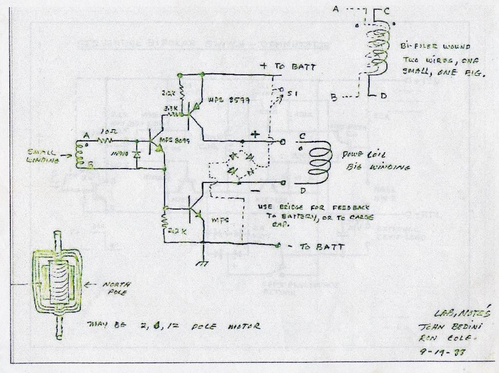
**Bedini/Muller-Combination
Since we know now from John Bedini how to use a byfiler wound stator coil with trigger wire for timing the transistors to create rotation to drive the wheel/rotor we can implement it in Bill Muller's set up instead of Hall Effect sensor switching where one uses little magnets on the rotor for the stator drivers which is another method used for timing. Using magnetic sand for the stator coil cores for quick release of the magnetism is a must with neodymium magnets on driving coils to prevent core saturation. Then use the, not back EMF, but the collected aether or better radiant potential resulting out of the abrupt tension collapse in those driving coils while rectified through pulsed caps onto the commutator which is oscillating very fast between driving the rotor and super-charging the battery which runs these driving coils. Make sure not to load the caps more than 5 times the battery voltage, which is also the magneto voltage and why John Bedini used 6 coils (approx. 60V) to run a 12V motor for a magneto driver, for safety. Don't drain the photo caps more than to the battery level each time you pulse them into a battery or batt. bank. If you hit a battery with too high of a voltage spike you are liable to blow it up!! Saturation on steel (welding rod) cores of the coils when using neo's is the reason John Bedini used ceramic ferrite magnets hence you can build a Bedini set up more cost efficient.
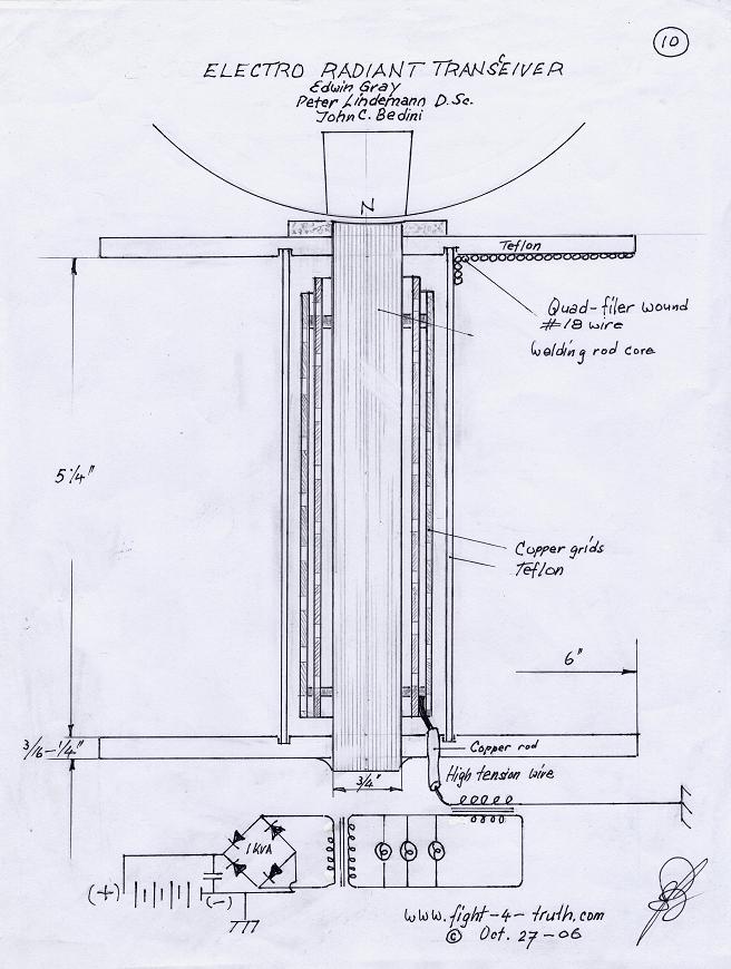
Image 14 Radiant Monopole motor Posted: October 28th 2006

Monopole Motor with Electro Radiant Transceiver
I baught and read "The Free Energy Secrets of Cold Electricity" a book by Peter Lindemann D.Sc. and came to the following understanding: The electro-radiant charge-receiving grids in Edwin Gray's conversion element switching tube is accepting a radiant charge due to a energy shock at the time of the spark in the spark gap at the voltage collapse. Power is raised in Gray's setup from the battery via a cap to 3000 volts DC clipped by a wacuum tube with a impulse duration of less than 50 microseconds through the spark gap, creating explosive radiant electrostatic fields of spatially-distributed voltage which is picked up by the charge receiving grids. In the Monopole motor we do not have 3000 volts, but we have between 150 and 400volt spikes at the time of the field collapse which I assume also results in energy shocks creating explosive radiant electrostatic fields of spatially-distributed voltage all along the rod-core of the coil, hence the reason for mounting the electro-radiant charge-receiving grids right in the center of the Monopole motor. Perhaps I am mistaken in my theorizing, although my feeling or inner voice tells me I am not very far off. I'll build it as soon I can manage some free time. In the mean while others might want to give it a try or get the parts for it since there is more than one way to saddle this horse and I think the sooner anybody does it the better. Rumor has it that Bush is planning to drop the US dollar to 50 cents shortly. If this comes true then look out!!!
Puzzled? Is image 14 oversimplified? Don't take my word for it and learn of the wonderful performance of cold electricity, it is not cold as it sounds which promises excitement especially considering that this high voltage you can touch since it does not burn or kill, except from capacitors, which is contrary to what we read about the HV discharge of standard Tesla coils we see on the net. Read of the amazing transformer/converters developed by Nikola Tesla and Edwin Gray, which Peter explains and describes so thoroughly in his book.
Here is what you've been waiting for: http://www.cheniere.org/books/FEG/index.html
John Bedini and Tom Bearden's new book ,
or http://truthinheart.com/order1.html for $33.12
John Bedini's Cole-Bedini (window) Motor, an other gift of him to the people
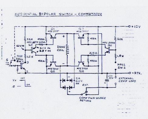
Image 15 I call it: "Torquy" Posted: November 17th 2006

When you build your first window motor use a steel shaft through an armature core of hexagon steel and neo magnets with three coils complete using Hall's preferable for the switching, you have to switch both the N and the S. Use the Cole Bipolar schematic for now, perhaps later on I will be able to show you the full Cole-Bedini Motor schematic and more of John's drawings. I will wind my first three coils bifiler #18/23AWG, that way I am not committed to hall switching. If you switch it properly you can make it run itself. Just use a big capacitor and let the motor charge the capacitor while you spin it, by tapping either coil for the AC, incl. the red one, at different times over a full wave bridge rectifier (FWBR) to the capacitor with the running leads of the motor also hooked to the capacitor...... Yes, there is two ways of self running this motor. 1st. With commutator switching from the energizer back and forth between battery and motor. Keep in mind that you can't charge a battery while extracting energy from it at the same time without destroying it like they do in cars. 2nd. Tapping AC from one or more coils via FWBR directly into a big capacitor while running the motor from that capacitor. -- If you are wise, then you know how you have to handle this new gained knowledge!! Ron Cole apparently wasn't and drank himself to death as a result!....... Work it, and keep an eye on the voltmeter, until the motor runs itself. Also keep an eye on the charging capability while you are testing it. Work it until you have it. I can guarantee you that it works. Don't forget the big wheel for kinetic energy to give the motor momentum, the bigger the radius of it the better. If you can install a pulley to pull start the motor it would help a lot. John Bedini demonstrated it to us with one coil by just rotating the rotor by hand. Make sure the magnetic poles are N and S in line, the N-pole is switched on the N-pole side of the "A" field of the coil while the S-pole is also switched on the opposite "A" side of the same coil. It is entirely possible that the coils which are setup "in phase" are in charging mode on one capacitor while a second coil marked in red "out of phase" is running the motor from another capacitor!!! I am far from an E. engineer, but flexible thinking helps :). Through trial and error I will get to where I am headed, so be patient with me when you see blunders I am making. I'll fix them as I see them.
The commutator in image 15 above, which is my design, is a mechanical switch, it works with HV if you can keep the brushes from burning up at high voltage. The SSG or window motor is just a mechanical way of triggering this radiant energy and the copper wire is the collector of it, and it closes the loop to charge the battery.
I built the commutator or better on-off-switch in a similar way as I pour my little rotors/spools. I'll have a write up in my work shop later on some times. I used two sizes of copper pipe. One I cut in an angle clear across, the other bigger one I silver soldered the inside "ID" and machined it out to the same OD as the commutator and cut it into segments for the brushes.
You need to use two 1/4 NC set screws in the epoxy from both sides, that way you don't have to tighten them too much. Don't use more than 10% talcum powder or none at all in the resin in this case depending on size, just cool it in cold water while it is hardening if you can't touch it anymore. If you strip the threads, drill it up to 1/2NC, pour the bore with straight resin again and re-cut the 1/4 NC thread, it's easy, it cuts like cheese :).
In continuation of the replication page, I must tell you that I changed a few things around. First I removed all the wires from my 8-coiler, left two coils and removed the others. Squashed a couple of 1/2" copper pipes, didn't have any 3/4 K-copper, which is the stuff the plumbers use for H2O house service lines (heavy wall pipe, match the cross sections of the twisted wire), then I soldered up four transistors according image 8 above, used two #8 wires for bus bars off the transistor terminals, pos. and neg. each, ensuing the two coils in parallel and set everything up. Anyhow I'm getting ahead of myself, the drawing above is the result of my new setup.
Another reason for piggy backing a second coil to one plate is having looked at the "Big Boy".
Looking at the book, multiplying the single SSG transistor did not make any sense to me at first, until I mounted all four on the plate and studied the setup. That some transistors have a negative resistance region, has come across clearly, but how to comprehend it, is another thing. Never the less, perhaps picking the energy up through the switching transistors into the bus bar, instead direct off the plate, like I have been doing it, might speed up the whole operation. Realizing that two or more bipolar transistors hooked up in parallel might have an amplification effect like a differential amplifier, which would not really surprise me knowing that John Bedini is a specialist in transistor amplification. Thus I hooked up the four transistors and everything according my feelings (the Lord's help), with the same ohm setting for max. VAC output off the coils (from before with one transistor setup only, since I never managed the wheel to reach the sweet spot) and gave the 12" 8-mag wheel a good spin by hand. When I flicked the switch, the wheel took right off like I gave it a kick and so did the needle of the charging voltmeter. At first the motor drew 4.5 amps then it dropped down to 3.8 then to 3.0 then it settled to the sweet spot at 2.5 amps just-a-hummin.. with a charging reading into the batteries at 0.3amps. Besides my pounding heart of joy, I was getting quite worried, whether my feeble wheel would stand this high RPM with those big magnets, the mags didn't have much gluing surface and my copper strapping was not very tight either... it was really creating wind. I ran it for about an hour, taking some readings at 4.30 in the morning.
Image 8a
You can see that I am not to far off by this next image 8a, which is the basic (small) proper schematic for this machine (Icehouse) which John Bedini just gave out. It also testifies of the forgiveness of little mistakes or changes without sacrificing too much output or efficiency of this machines, see my report at Image 3 (SSG) above. Once you work it you get better while you stay at it!
The big crash
Some hours later; no sooner the wheel was up to full speed it stopped with a big crash...the result? More work! Just because I was too tired to pay attention. If I would have looked it over first, I probably could have prevented a bent shaft and the two wrecked coils.....Here are the pictures:
Image 9
The coils look worse as they are, I rebuilt them already, for the wheel ? I will park it permanently.
Image 10

Image 11 (see SSG4 ICEHOUSE without the steering cam)
See comment on replication page 2
Image 12
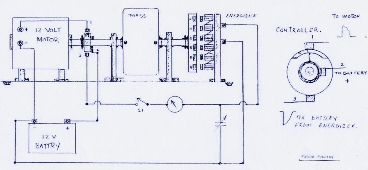
The torquy and efficient window motor with SSG type Bedini/Cole switching, Image 6a, or JB's lab notes, is the idea instead of the standard 12V motor above. Having built the SSG B/C it will be a breeze for you now to construct a window motor (not car window see image 15) and extending the shaft as shown above, the motor will run itself fed by the battery which recharges itself, if you setup the commutator right that is, like John said, you have to do a little tinkering to get it to work!! The advantage of the window motor producing its own scalar-power is resulting in full usable output of the magneto or generator. Use SS or brass shaft, 6x6" long plastic rotor and 6 1x1x6" long or better yet 2" super pole neo magnets since we have no iron core. The impedance of this motor is very low start with 400 feet depending on your battery size 1 to 4 #18 1 # 23awg magnet wire per window coil or scip the smaler wire and use hall trigger. Remember more windings = more RPM/Volts stronger spikes, less primary draw. More wires twisted as one wire "Lize", brings down the impedance!
Study Image 12 and construct a controller with brushes switching from the motor driver to the rectified back EMF/radiant energy mix of the widow motor onto copper and epoxy (commutator) on and off to the battery which process has to be fast enough to make it work, like the commutator above or image 15 below. Very effective, no components to burn out, no sparking, it will handle any amount of current you'll ever need! If you are interested, Rick Friedrich sells John Bedini's booklet on this generator for about 20.- US-Dollars. It is worth every cent of it.
On the energizer side for preventing locking up (Bill Muller), use an odd number of, this time, neodymium magnets while winding an even number of stator coils in series with 20AWG magnet wire at 250 turns each while like Bill Muller using magnetic sand as the core for extra big voltage spikes and magnet repellent kick, with a stainless steel coil mounting screw, or cast iron cuttings (machine shop) as a second and lesser option although in our case we probably can get away with it not having to worry to much about core saturation** no doubt but having to sacrifice quality on the voltage spikes. According to Bill he used 3mm magnetic wire on his coils because of the high current with a limited amount of windings using three coils for driving the rotor by means of bipolar transistors etc. timed with small magnets on the rotor of his machine which I witnessed myself as he demonstrated it to me and my brother, he might have used thinner wire on the stator coils to drive his rotor. I recall clearly that his approx. 24" rotor didn't turn all that fast while he demonstrated high current and high torque, brother couldn't slow it down with one of Bill's rags in his hand.
Make yourself a core mold with grooves for the bobbin sides with a greased up ss-screw in the center of it and mix the black sand/cast iron cuttings with 50/50 epoxy to a thick paste before filling the mold, keep in mind that the sand or filings will be settling to the bottom of the core-mold within the epoxy-mix if you don't do it right.
Black sand
The possibility of finding it is not very great. I found some near a city along the beach of a lake in the interior of BC. A good place to find it is on mining sites or rivers. A prospector says: "I run a 3.5 ton per hour dry washer and at the end of the day I have several 5 gallon buckets of pure black sand". The desert fox automatic gold panning machine is a method of acquiring black sand by hand in a hurry. An other way is take a 2” neo magnet inside a plastic bag and drag it over sand in different locations until you find some pay dirt. Turn the bag inside out and you have a clean magnet and the magnetic sand inside your bag.
Just because you find some black sand does not necessarily indicate magnetic sand. Also the quality of strength in magnetic sand varies greatly. You have good quality sand if it builds up like porcupine quills on the magnet. Black sand is composed of different minerals of black grains and sometimes even white crystal grains of magnetite. The easiest way to separate the weak from the strong magnetic minerals is by building your self a 45 degree acrylic shoot with first and second 2" neo magnets (you need them anyway for the generator side) fastened on top of it by a hinge for releasing it through the Plexiglas once you have enough accumulation on the magnets. You need a 2mm variable slot on the bottom of the hopper and a 10mm variable drop down plain in front of each magnet on the shoot . I'll place a picture once my film is full.
**Bedini/Muller-Combination
Since we know now from John Bedini how to use a byfiler wound stator coil with trigger wire for timing the transistors to create rotation to drive the wheel/rotor we can implement it in Bill Muller's set up instead of Hall Effect sensor switching where one uses little magnets on the rotor for the stator drivers which is another method used for timing. Using magnetic sand for the stator coil cores for quick release of the magnetism is a must with neodymium magnets on driving coils to prevent core saturation. Then use the, not back EMF, but the collected aether or better radiant potential resulting out of the abrupt tension collapse in those driving coils while rectified through pulsed caps onto the commutator which is oscillating very fast between driving the rotor and super-charging the battery which runs these driving coils. Make sure not to load the caps more than 5 times the battery voltage, which is also the magneto voltage and why John Bedini used 6 coils (approx. 60V) to run a 12V motor for a magneto driver, for safety. Don't drain the photo caps more than to the battery level each time you pulse them into a battery or batt. bank. If you hit a battery with too high of a voltage spike you are liable to blow it up!! Saturation on steel (welding rod) cores of the coils when using neo's is the reason John Bedini used ceramic ferrite magnets hence you can build a Bedini set up more cost efficient.
Image 14 Radiant Monopole motor Posted: October 28th 2006
Monopole Motor with Electro Radiant Transceiver
I baught and read "The Free Energy Secrets of Cold Electricity" a book by Peter Lindemann D.Sc. and came to the following understanding: The electro-radiant charge-receiving grids in Edwin Gray's conversion element switching tube is accepting a radiant charge due to a energy shock at the time of the spark in the spark gap at the voltage collapse. Power is raised in Gray's setup from the battery via a cap to 3000 volts DC clipped by a wacuum tube with a impulse duration of less than 50 microseconds through the spark gap, creating explosive radiant electrostatic fields of spatially-distributed voltage which is picked up by the charge receiving grids. In the Monopole motor we do not have 3000 volts, but we have between 150 and 400volt spikes at the time of the field collapse which I assume also results in energy shocks creating explosive radiant electrostatic fields of spatially-distributed voltage all along the rod-core of the coil, hence the reason for mounting the electro-radiant charge-receiving grids right in the center of the Monopole motor. Perhaps I am mistaken in my theorizing, although my feeling or inner voice tells me I am not very far off. I'll build it as soon I can manage some free time. In the mean while others might want to give it a try or get the parts for it since there is more than one way to saddle this horse and I think the sooner anybody does it the better. Rumor has it that Bush is planning to drop the US dollar to 50 cents shortly. If this comes true then look out!!!
Puzzled? Is image 14 oversimplified? Don't take my word for it and learn of the wonderful performance of cold electricity, it is not cold as it sounds which promises excitement especially considering that this high voltage you can touch since it does not burn or kill, except from capacitors, which is contrary to what we read about the HV discharge of standard Tesla coils we see on the net. Read of the amazing transformer/converters developed by Nikola Tesla and Edwin Gray, which Peter explains and describes so thoroughly in his book.
Here is what you've been waiting for: http://www.cheniere
or http://truthinheart.com/order1.html for $33.12
John Bedini's Cole-Bedini (window) Motor, an other gift of him to the people
Image 15 I call it: "Torquy" Posted: November 17th 2006
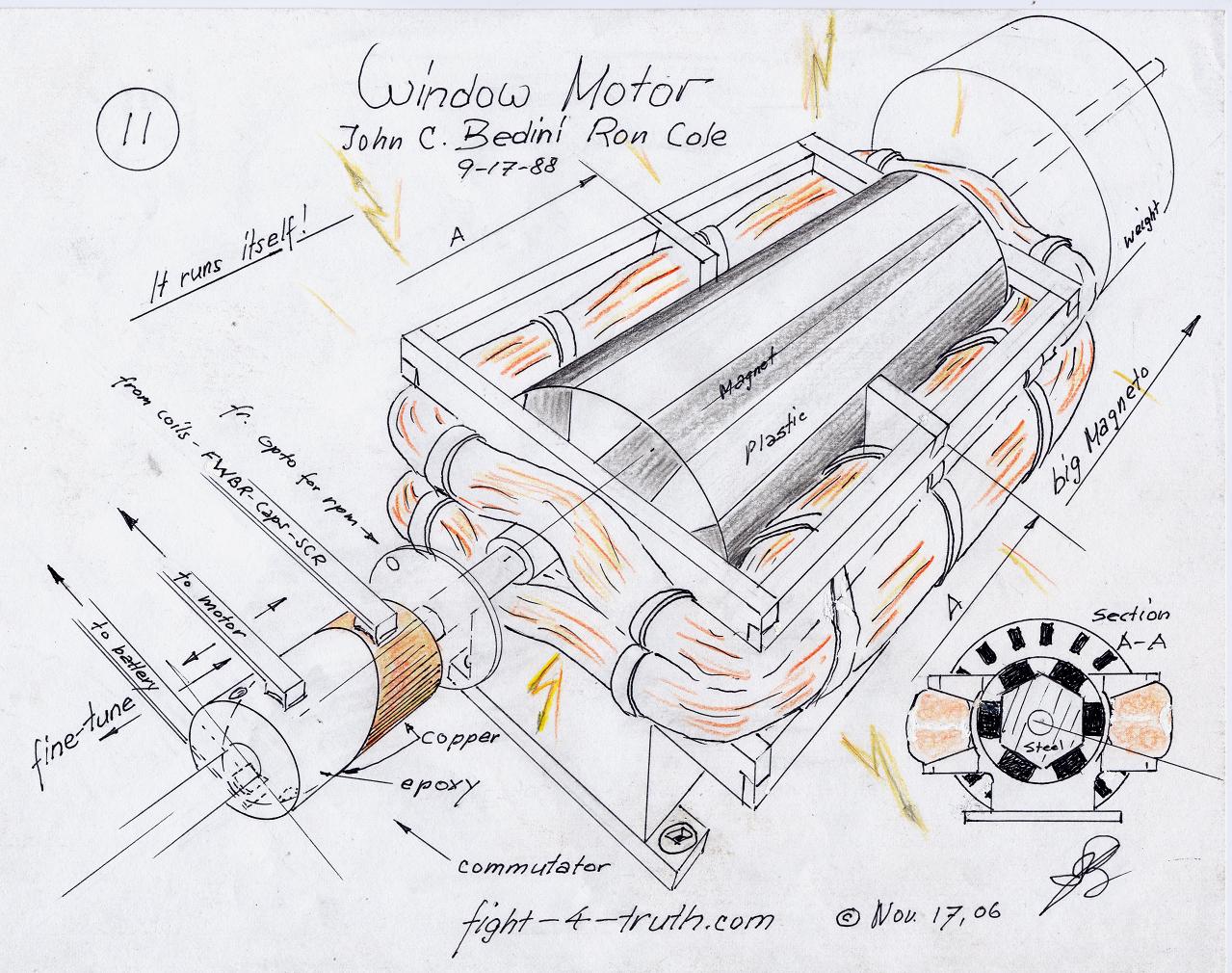
When you build your first window motor use a steel shaft through an armature core of hexagon steel and neo magnets with three coils complete using Hall's preferable for the switching, you have to switch both the N and the S. Use the Cole Bipolar schematic for now, perhaps later on I will be able to show you the full Cole-Bedini Motor schematic and more of John's drawings. I will wind my first three coils bifiler #18/23AWG, that way I am not committed to hall switching. If you switch it properly you can make it run itself. Just use a big capacitor and let the motor charge the capacitor while you spin it, by tapping either coil for the AC, incl. the red one, at different times over a full wave bridge rectifier (FWBR) to the capacitor with the running leads of the motor also hooked to the capacitor...... Yes, there is two ways of self running this motor. 1st. With commutator switching from the energizer back and forth between battery and motor. Keep in mind that you can't charge a battery while extracting energy from it at the same time without destroying it like they do in cars. 2nd. Tapping AC from one or more coils via FWBR directly into a big capacitor while running the motor from that capacitor. -- If you are wise, then you know how you have to handle this new gained knowledge!! Ron Cole apparently wasn't and drank himself to death as a result!....... Work it, and keep an eye on the voltmeter, until the motor runs itself. Also keep an eye on the charging capability while you are testing it. Work it until you have it. I can guarantee you that it works. Don't forget the big wheel for kinetic energy to give the motor momentum, the bigger the radius of it the better. If you can install a pulley to pull start the motor it would help a lot. John Bedini demonstrated it to us with one coil by just rotating the rotor by hand. Make sure the magnetic poles are N and S in line, the N-pole is switched on the N-pole side of the "A" field of the coil while the S-pole is also switched on the opposite "A" side of the same coil. It is entirely possible that the coils which are setup "in phase" are in charging mode on one capacitor while a second coil marked in red "out of phase" is running the motor from another capacitor!!! I am far from an E. engineer, but flexible thinking helps :). Through trial and error I will get to where I am headed, so be patient with me when you see blunders I am making. I'll fix them as I see them.
The commutator in image 15 above, which is my design, is a mechanical switch, it works with HV if you can keep the brushes from burning up at high voltage. The SSG or window motor is just a mechanical way of triggering this radiant energy and the copper wire is the collector of it, and it closes the loop to charge the battery.
I built the commutator or better on-off-switch in a similar way as I pour my little rotors/spools. I'll have a write up in my work shop later on some times. I used two sizes of copper pipe. One I cut in an angle clear across, the other bigger one I silver soldered the inside "ID" and machined it out to the same OD as the commutator and cut it into segments for the brushes.
You need to use two 1/4 NC set screws in the epoxy from both sides, that way you don't have to tighten them too much. Don't use more than 10% talcum powder or none at all in the resin in this case depending on size, just cool it in cold water while it is hardening if you can't touch it anymore. If you strip the threads, drill it up to 1/2NC, pour the bore with straight resin again and re-cut the 1/4 NC thread, it's easy, it cuts like cheese :).
Cole-Bedini
Motor update
Be aware that this Motor can be setup and switched in a number of different ways. Also be aware that we have been riped off by the elite cartel right to the very basics in how to run a generator. If a certain generator is set up with "two more coils" 90º apart with a capacitor the generator can be operated as a motor/generator running itself after it has been started with a pull cord!!! Remember that I titled my website "fight-4-truth"!
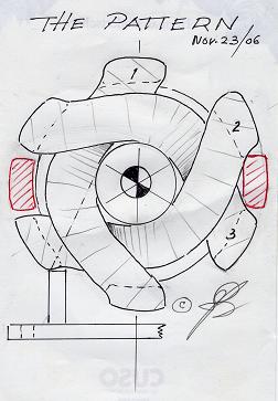
Image 16
 This is a front view of the window motor
with three coils. You have to make yourself a wooden jig to wind the
wire onto in order to get the proper shape of the coil, which is wide
on one side and narrow on the other. The marked coil in red is a 90º
added coil in testing at the moment. I tell you why with this story:
This is a front view of the window motor
with three coils. You have to make yourself a wooden jig to wind the
wire onto in order to get the proper shape of the coil, which is wide
on one side and narrow on the other. The marked coil in red is a 90º
added coil in testing at the moment. I tell you why with this story:
I am not sure whether the person who told this story would take it kindly if I use his name here, hence I never asked him, I'll leave it out. It is also an example of the satanic cowardly ways the elite use to oppress or kill a soul for not cooperating. Enough prove for the story being true is the demonstration of self running the window motor :

Be aware that this Motor can be setup and switched in a number of different ways. Also be aware that we have been riped off by the elite cartel right to the very basics in how to run a generator. If a certain generator is set up with "two more coils" 90º apart with a capacitor the generator can be operated as a motor/generator running itself after it has been started with a pull cord!!! Remember that I titled my website "fight-4-truth"!
Image 16
 This is a front view of the window motor
with three coils. You have to make yourself a wooden jig to wind the
wire onto in order to get the proper shape of the coil, which is wide
on one side and narrow on the other. The marked coil in red is a 90º
added coil in testing at the moment. I tell you why with this story:
This is a front view of the window motor
with three coils. You have to make yourself a wooden jig to wind the
wire onto in order to get the proper shape of the coil, which is wide
on one side and narrow on the other. The marked coil in red is a 90º
added coil in testing at the moment. I tell you why with this story: I am not sure whether the person who told this story would take it kindly if I use his name here, hence I never asked him, I'll leave it out. It is also an example of the satanic cowardly ways the elite use to oppress or kill a soul for not cooperating. Enough prove for the story being true is the demonstration of self running the window motor :
To All,
During world war two, two GI's wandered into a little town in Germany
During world war two, two GI's wandered into a little town in Germany
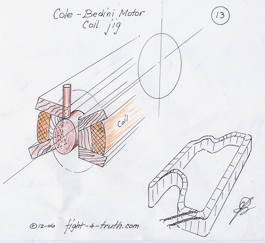
While
you design your own jig, use a wood dowel the whole length in the
center of the jig with an outside diameter by adding 1/8th to the OD of the magnet
rotor which would give you the inner
radius of the coils . Add a small wood plug at the end of the
big dowel for clearance of the coils over the rotor shaft. Keep in mind
not to glue, but to bolt
down the top two wood plates in order to remove the wound coils after!
When you install the coils build a frame around the coils/motor for tying them to it for rigidness.
My latest SSG
I just built a new SSG circuit according to JB’s newest multi coil schematic, while using a 300 ft 6 - 18AWG and 1 - 23AWG mag wire coil and 14 - 100uf 330V caps. This time I connected the six wires directly to each transistor terminal collector of all 6 - MJL21194’s. When I checked the heat sink with the acustic circuit tester for sound the following occured: No buzzing sound but instead, interestingly and to my delight, the circuit was oscillating solid state, without the rotor moving, with the rheostat cranked up to 230Ohms, charging two 1000CCA batteries a tenths of a volt every 35 seconds for a while. There was quite an audible clicking sound present at the SCR (16RIA80). I left the two batts charge over night from 12.62V to14.26 and noticed the next day that the deep cycle marine driver only dropped two tens of a volt!!
Although the circuit had been running by itself, but once I hooked the LED back up and pressed the start button I had no rotation not even the LED lid up, nothing, all nail dead zilch zero!!
I have spent hours in finding why I Can't get the MJL21194 transistors to fire properly. This happened to me once before when shortening out the system by reversing the battery terminals by mistake while experimenting carelessly. Not until I exchanged all transistors could I get it running again.
Although this new case is entirely different I did unsolder all transistors to check them all for proper Ohm reading again. The familiar transistor firing buzz sound is missing right from the start, while the LED hooked to the coil leads, tells me the firing stroke now though. RPM is barely there, right down to 1.8 Ohm of the resistance values.
To struggle with this kind of problems is tough realizing only to well the practical handicap of the present lack of experience. John Bedini has over 30 years experience in this while I can boast of hardly two years, hah…now we just have to buckle up and prove worthy of the gifts presented by John, he didn’t say for no reason, there is no such thing as free electricity.
It looks like the problem is in the 0.6V biasing voltage, proper resistance and timing needed to permit current to flow through the collector-emitter channels of the bipolar transistors to give the rotor the kick needed to rev up.
I went back to square one experimenting with one transistor and zero caps on this circuit. I will work it until I have it, then I will slowly add the rest to it one by one, like I did previously.
I ended up using one of my other rotors and coil. Not until I dumped all resisters I got rotation at 0.5 Ohms on the trigger to the base where I used 6 #23AWG wires to the different transistor bases from the rheostat, I also found better performance by mounting all six wire strands to the heat sink instead to the transister collector terminal. The funny thing is once I had it running at the sweet spot at 66 Ohms, the rotor will now start without any trouble!! Even though I moved up and dow the resistance paths I still missed the little operating window. I did try to set proper biasing voltage to the transistors, without success.
Magnetic interference with steel on the rotor like the 10x30mm bearings and steel shaft was part of the problem with the other rotor. I should have known to stick to smaller bearings 8x20mm and aluminium or brass shafting. My main problem was the two aluminium bearing supports in close proximity to the rotor. Plastic or wood is the answer.
I also wash the grease out of my bearings and use same oil as I use on my diesel engines which is a 15-40 multi grade. For superior friction reduction a few added drops of BITRON seams to work well.
I My First SG Replication I Work Shop I Parts Page I
Last
update of this section: February 8, 07
This website is under construction!
The URL of this page:
http://www.fight-4-truth.com/Schematics.html
http://www.fight-4-truth.com/Schematics.html